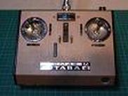
Futaba M-Series Refurbishment
October 2008
For those unfamiliar with the issue, it's thought that as the transmitter battery pack ages, it causes corrosion in the wiring from the battery to the switch, and sometimes beyond. The actual cause of this is a matter of some debate. However some believe this is as a result of electrolyte leakage from the nicads creaping form the cells along the conductor within the PVC insulation (http://www.rcbatteryclinic.com/blkwire.html).
|
The only practical solution this problem is to replace the nicad pack, the affected wiring, and more often than not, replace the switch.
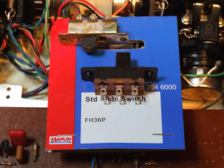
Here in the UK, Maplin Electronics (http://www.maplin.co.uk) stock a DPDT slide switch with the required 28mm fixing centres (http://www.maplin.co.uk/module.aspx?ModuleNo=2483&doy=29m7), and is an excellent candidate to replace the original Futaba power switch. |
At the time Model Power stocked a good range of replacement transmitter packs, and a 9.6v, 2400mAhr square section pack was sourced from here.
Component Shop (http://www.componentshop.co.uk), also stock a similar range of rechargeable battery packs, which can be found here: http://www.componentshop.co.uk/batteries/radio-control/transmitter.html Removal and replacement of the switch is a delicate operation. The nuts, securing the screws, are a little fiddly to remove and an appropriately sized nut spinner can help. The screws are secured with thread lock, so careful use of a good fitting screwdriver can prevent damage to the heads of the screws. A small modification had to be made to the switch, requiring 1-2mm to be removed from one of the mounting tags, to enable the switch to fit. It was found that replacement of the switch is made easier by removal of the power meter. |
After replacing the switch and affected cabling, specifically from the switch to the PCB, the switch to the charging socket, and the switch to the battery, the transmitter was tested successfully.
The next job was to adjust the pulse width timing to bring the M series into line with modern servo timing. To explain, older radio gear prior to 1985 or so, used a pulse width of 1.3ms for the neutral position of a servo, later equipment used a pulse width of 1.5ms. Also on the receiver end, compatibility between older and later Futaba equipment is further complicated by Futaba changing the plugs and sockets from the 'G' type to the 'J' type.
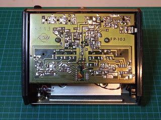
The timing adjustment of the M series transmitter requires each channel to be adjusted individually. From the image above, the M series circuit board identifies which trim pot adjusts the timing of which channel. To check and modify the timing adjustments, an oscilloscope was connected to each channel of the receiver in turn, and the pulse width measured. The original timing was measured at a nominal 1.35ms at neutral, down to 0.85ms, and up to 1.8ms. Adjustment of the trim pot for each channel resulted in a nominal 1.5ms at neutral, down to 0.9ms, and up to 2.1ms.


